Table of Contents
Engine operation and ECU tuning concepts
It's simply impossible to give a full account of engine operation and ECU tuning concepts in a couple paragraphs. So please don't take the following as a complete summary of everything involved. It's not. This section is simply intended to orient the reader's mindset in the right direction with some high level concepts.
The engine works by igniting a mixture of air and fuel. The ratio of air to fuel is a key ingredient in producing power. Too much air or too much fuel (or too little of either) causes poor running conditions, misfires, etc. The mechanism used to ignite the mixture is a spark from the spark plug. The exact timing of this ignition process relative to piston position is another critical item in producing power. This is call “timing” or “ignition advance”.
The whole process of injecting fuel in the right amount related to the amount of air going into the engine and firing the spark at the exact right moment is all coordinated by the ECU. The ECU needs to know how much air is entering the engine to know how much fuel to inject. It also needs to have some idea of how much cylinder pressure is involved to schedule ignition advance appropriately.
Air flow
The amount of air going into an engine is a critical piece of information the ECU needs to know very accurately so that it can accurately calculate how much fuel to inject. If the real airflow going into the engine is different from the amount the ECU thinks is going into the engine, the ECU will schedule an inappropriate amount of fuel and the engine's operation will suffer as a result. So accurate airflow metering is really important.
Things that can contribute to inaccurate airflow metering include intake air leaks (blown couplers, leaky seals, etc.) or just simply an airflow sensor that's reporting inaccurate values. Stock Mitsubishi airflow sensors generally need little adjustment, assuming they are installed properly and have a nice long, straight path for air in front of the sensor. Installations with 90 degree bends right at the MAF inlet or mushroom style air filters can cause inaccuracies even with otherwise stock Mitsubishi MAF sensors because both change *how* the airflow passes through the metering section of the MAF.
Installing a non-stock MAF like a GM MAF is a whole 'nother can of worms. Suffice to say it can be done, but can require even more attention to detail to keep the airflow reported to the ECU as accurate as possible.
The bottom line is that you need accurate airflow readings to the ECU if you want the ECU to inject accurate fuel.
Fuel flow
From the amount of air the ECU is told is going into the engine, the ECU calculates an amount of fuel required to maintain a 14.7:1 A/F ratio using stock injectors at stock fuel pressure. This is where things can get a little tricky to keep straight in your head. The ECU is coded from the factory to account for the configuration the engine came with from the factory. That is, stock injectors and stock fuel pressure. On a stock 2G DSM, that's 450 cc/min injectors at 42.6psi base fuel pressure. On a stock 1G manual DSM, that's 450 cc/min injectors at 37psi. Stock 1G automatics came with 390s at 42.6psi. This determines the flow rate of fuel into the engine. From that flow rate assumption, the ECU can calculate how long to hold the injectors open to get a specific mass of fuel required for the mass of air it believes is coming into the engine.
So, you have two things now that the ECU needs to have accurate information on. First, it needs accurate airflow to calculate fuel flow requirements and second, it needs to know if you've changed anything that affects fuel flow into the engine. If you change base fuel pressure or you swap in different injectors, you have to adjust the ECU's fuel flow calculations to take this into account.
There are two “modes” of operation for fuel control. In both cases, the ECU starts out with airflow data from the airflow sensor and calculates a 14.7:1 A/F ratio using its assumption about injector size and fuel pressure. But in “closed loop” mode, it checks to see how far off this estimate was by monitoring feedback from the O2 sensor. Closed loop mode is typically active during idle and cruise conditions.
In the other mode, “open loop”, it does not check these assumptions. It simply calculates fuel flow requirements and injects fuel. This is the mode the ECU operates in at wide open throttle and a few other conditions (early start up for example).
Closed loop
Closed loop mode is explained in more detail on the Fuel Trims page. Please read this page and really understand how fuel trims play a role in closed loop mode of operation. They are very important numbers when it comes time to dial in a new set of injectors, for example.
Open loop
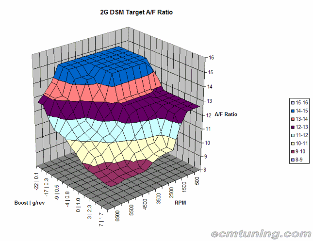
When the ECU is running in open loop mode, it still starts with a 14.7:1 estimation of air/fuel ratio, just as it does in closed loop mode. But then it applies an enrichment factor based on a table look up. This factor will almost always add more fuel to the mixture. So instead of a 14.7:1 air/fuel ratio (A/F), the ECU may try to run 9.5:1. As you increase fuel, you increase the denominator in the air/fuel ratio and as a result you decrease the ratio value. This ratio is said to become “richer” as you add fuel. It becomes “leaner” as you take fuel away.
The “closed loop” target of 14.7:1 is called the stoichiometric ratio for gasoline. This ratio is the theoretically “ideal” mixture where all fuel is combined with all the free oxygen exactly. This is the ratio the ECU targets under light load conditions (idle/cruise). But it is inappropriate as load increases. As engine load increases, it generally becomes less tolerant of “lean” mixtures. Trying to run an engine too lean for the operating conditions can cause things to melt or can cause the combustion process to break down and “explode” rather than burn (typically called detonation or knock). So it's important to keep the mixture rich enough to prevent this but lean enough to make decent power.
So when running “open loop”, the ECU does not always target 14.7:1. It targets an A/F ratio that depends on load and RPM. The picture below illustrates what this type of target table looks like. You can see that as RPM and load increase, the target A/F ratio gets richer and richer.
Timing (ignition advance)
At some point, air and fuel is going into the engine and getting all mixed up and pressurized by the piston going up on the compression stroke. The ECU then schedules the ignition of that mixture. The precise point at which the ignition takes places is very critical. Firing too early (advanced too far) can cause very bad things to happen as cylinder pressures increase dramatically beyond design limitations and stuff starts to break. Firing too late (too retarded) generally just causes poor performance. So the trick is finding the happy middle ground.
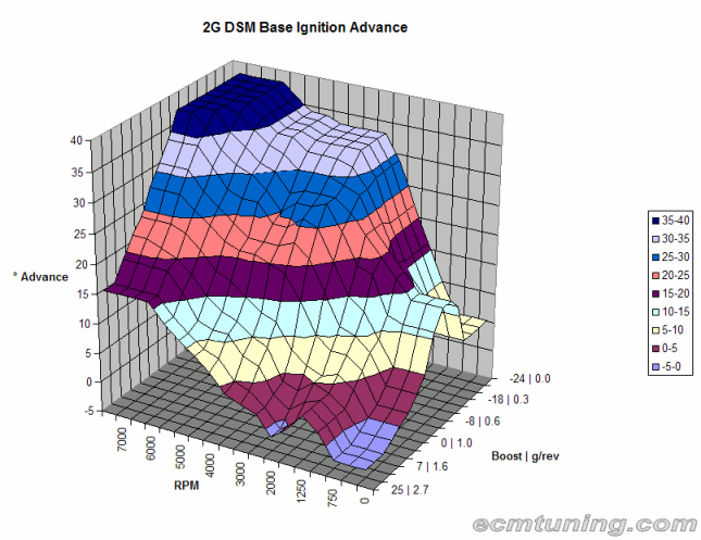
The ECU from the factory has a couple big tables it uses to look up basic ignition advance values. Those values, just like the A/F ratio values for fuel, are tweaked a bit based on operating conditions. But the bulk of ignition advance figures comes straight from the ECU's timing tables. As engine speed (RPM) increases, timing needs to increase as well. “Why” is a long story, but take it for granted that it does. As engine load (cylinder pressure) increases, timing needs to decrease. So these ignition tables are laid out with RPM on one axis and engine load on the other. The result looks something like the following. You can see that as load increases, timing decreases and as engine speed (RPM) increases, timing increases.


