This is an old revision of the document!
MFI Schematic - I/O
You can tell from the MFI schematic in the shop manual which pins are inputs and which pins are outputs from the ECU. This page explains how.
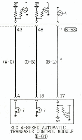
First, reference the 2G MFI schematic (or the 1G MFI schematic) for an example of what this schematic looks like in the Mitsubishi shop manual. The following is a clip from the 2G manual showing three connections between the ECU and the Automatic Transmission computer (TCU).
Look at pins 43 and 46 on the ECU side. You'll see a +5v pull up resistor on each input. That means, when nothing is connected to that input (or when the TCU output is “inactive”), the ECU's sense circuit will “see” 5v. Which means in order for the AT to “active” that input, it will need to switch the input to ground (which is what the transistor with a connection to ground illustrates on the TCU side).
This all clearly indicates that these pins are “inputs” to the ECU that the TCU is driving as “outputs”. So some function inside the TCU will request some function to be activated inside the ECU by pulling those inputs to ground.
And if you'll notice, the two circuits are reversed on ECU pin 7 (AT pin 17), which tells us that that particular connection is an output from the ECU that controls some function inside the AT computer.


