This is an old revision of the document!
Table of Contents
Non-EPROM Conversion Process
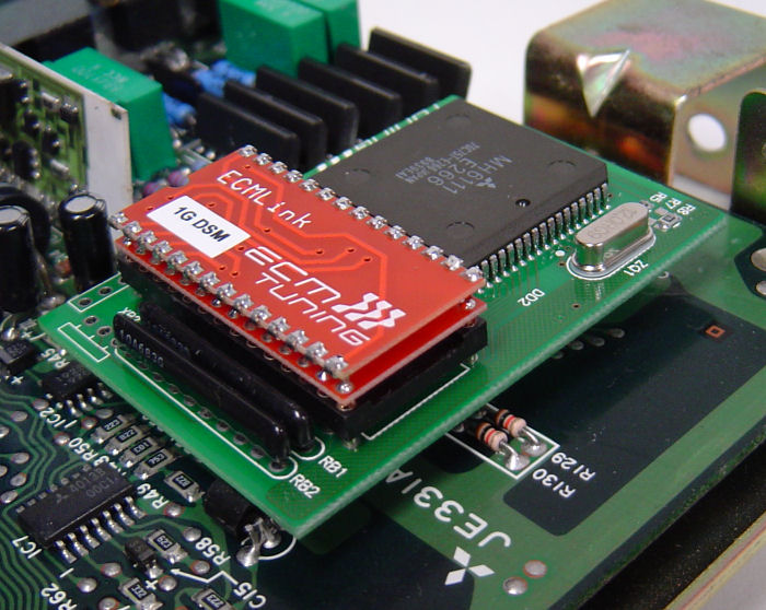
Someone asked us to explain what was involved in the non-EPROM conversion process and I thought it was a good question we hadn't covered before. This page outlines the basic process. This page shows the process on a 1G ECU, but the 2G ECU conversion process is very similar. The pin spacing is MUCH tighter and harder to work with on the 2G ECU, but the basic idea is the same.
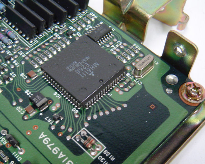
Initial Non-EPROM Board
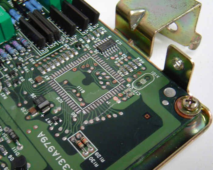
CPU Removed
The first step is to carefully remove the CPU and make a few other modifications to the ECU's PCB to prepare it for our conversion. The following picture shows a board after this step is complete (click to enlarge).
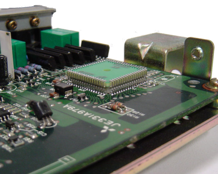
Adapter Plug
After the CPU is removed, we have to install an adapter plug in its place. The following picture shows a board after this step is complete (click to enlarge). Note the careful solder work involved on those pins.


