This is an old revision of the document!
Table of Contents
LC-1/LM-1 Installation Example
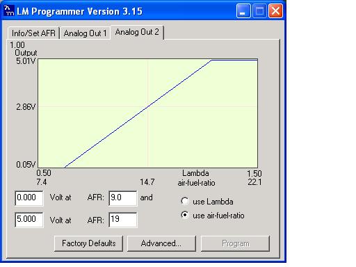
The Innovate LC-1 and LM-1 wideband kits are programmable units. That means the mapping of voltage output to A/F ratio can be changed by the user. Which means there's no default LC-1 or LM-1 item in DSMLink to datalog. So what we suggest you do is to program the output to mimic another device that we do support. Typically this would be the linear TechEdge output that has 9:1 mapped to 0v and 19:1 mapped to 5v. Then you would datalog this as the linear TechEdge (TEWBLin).
Details
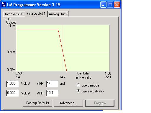
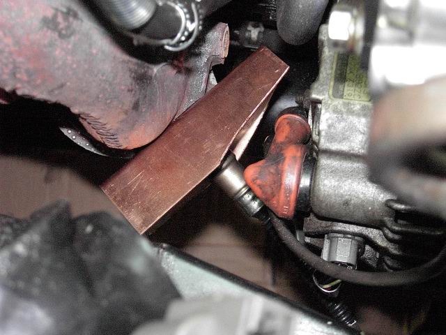
Scott McIntyre provided the following information on our user support forums for his install of the LC1 into the front O2 sensor bung. He uses the kit's narrowband output (analog 1) to drive the front O2 input for closed loop operation and then feeds the kit's analog 2 output to the rear O2 input on the ECU for datalogging wideband A/F ratio. The following are pictures he posted of his install procedure.
Analog out configuration
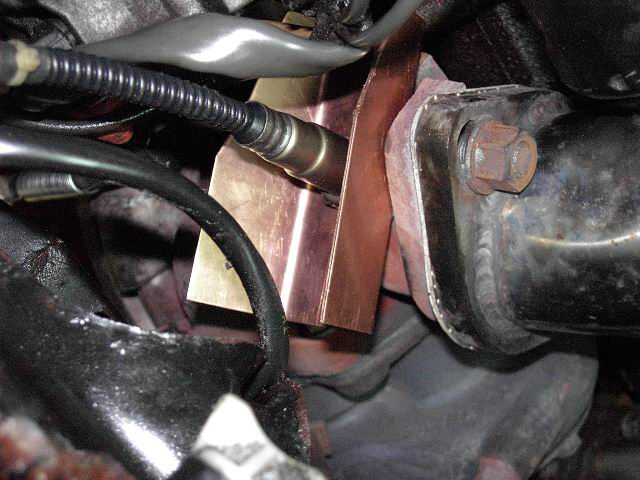
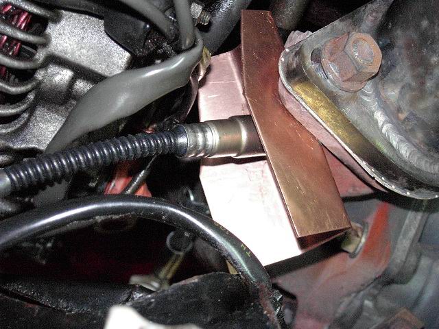
Copper heatsink fabrication
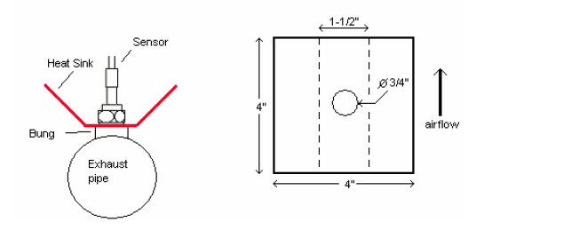
To aid in heat dissipation when the wideband sensor is installed in the front O2 location, a copper heatsink can be constructed. The following is taken from the Innovate install manual.
Use a 4“ x 4” (10cm x 10cm) sheet of copper sheet metal 14ga (1.5mm thick). Drill a hole in the center with the same diameter as the oxygen sensor threads (about 3/4“ or 19mm). Fold the sides up 45° and mount it between the sensor and the bung like you would a big washer. Orient it such that the sides are exposed to good airflow.

