This is an old revision of the document!
Table of Contents
Narrowband simulation
Wideband kits typically provide two distinct outputs. One is a 0-1v narrowband simulation and another is a 0-5v wideband output used for datalogging more precise A/F ratio data. You would typically run the narrowband output to the ECU's front O2 input so the ECU could run normal closed loop off this signal and then run the 0-5v output into a different ECU input for datalogging purposes.
With ECMLink's narrowband simulation function, you can simply run the 0-5v output to the ECU and then configure the ECU to produce the 0-1v simulation internally, thus freeing up an additional input on the ECU for some other aftermarket sensor.
Switch point
The help file included with the ECMLink application goes into detail about the process of configuring the NBO2 sim tab for your own setup. Please refer to this for more information. The best way to determine your own switch point is to datalog the wideband kit while running closed loop off a stock narrowband sensor and then simply take an average of the raw wideband voltage (available in the datalog as a Raw value) while the narrowband sensor is cycling normally. You can select such an area in your datalog with the mouse and then right click and do a “Selection→Average” to have the application average the values for you.
Some common stoichiometric (14.7:1) switch points are listed below.
| Wideband kit | Switch point (volts) |
|---|---|
| AEMWB | 4.07 |
| AEMWBGauge | 2.34 |
| AEMWBGaugeR1 | 2.53 |
| AFXWB | 4.07 |
| DynoJetWB | 2.94 |
| FJOWB | 2.5 |
| LC1WB | 2.44 |
| PLXWB | 2.35 |
| TechEdgeLinWB | 2.85 |
| TechEdgeWB | 2.5 |
| ZT2WB | 2.5 |
Startup options
Each WB kit “warms up” a little differently. You will need to adjust the startup options in the NBO2 sim tab to match your own configuration. To do that, fire up the engine while cold and monitor the WB kit's behavior as it warms up. It probably locks the value and probably takes a decent bit of time to warm up and start working. Watch this behavior and adjust the startup options in ECMLink accordingly to match your kit.
WBO2 sensor location
The best place to install the WBO2 sensor for accurate narrowband simulation is in the front O2 sensor location. This page outlines how one user installed his WBO2 in the front O2 location. When installed there, the WBO2 sensor can respond very quickly to the changes made by the ECU to A/F mixture. This is inline with assumptions in the ECU on how quickly it can expect to see a “response” as it adjusts short term fuel trim.
However, there are a number of situations where you may find it easier to install the WBO2 further downstream (in the rearO2 location on a 2G, for example). The problem is that the sensor responds more slowly to ECU mixture changes the further away from the engine it's placed. As a result, the ECU makes adjustments to the A/F mixture too quickly and “overshoots”, running really lean for a few seconds, then really rich, then lean, etc.
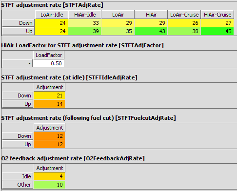
To correct for this, you need to change how the ECU adjusts the short term fuel trim. You do that in the STFTAndO2Feedback panel in Direct Access. The following illustrates a stock 2G DSM configuration.
You can try slowing the adjustment rates down (there are a lot of them) if you want. But your best bang for buck change will be to the O2FeedbackAdjRate table. Try values like 10 and 16 instead of the default values (4 & 10 shown above).


