Table of Contents
Using ECMLink's Generic (Linear) Display Items
Using pre-defined sensors
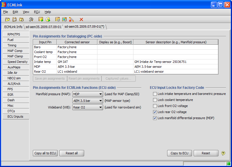
In order to datalog an aftermarket sensor in the ECMLink application, you must first tell the application where to find the sensor (which ECU input pin it's connected to). You do that in the “Pin Assignments for Datalogging (PC-side)” section of the ECU Inputs tab shown to the right (click to enlarge).
You basically tell the application which type of sensor is connected to which input. Then the application knows when it sees data coming from the ECU associated with that input, it can treat that data as if it were the redefined aftermarket sensor you selected in the drop down box instead.
We have pre-defined a number of common sensor calibrations for you. These include things like the Innovate LC-1 wideband, the GM 3 and 3.3-bar boost sensors, the AEM boost sensors, etc., etc. A complete list can be found on our Supported Aftermarket Sensors page.
A demo video also exists on our website showing how to use this dialog.
Defining your own
We have also provided a few “generic” items that let you define your own linear sensor types. These include the Linear boost, Linear fuel pressure and Linear wideband items in the Connected sensor drop down list.
When you select one of these generic items, you must tell the application about the sensor's mapping of volts to output value. You'll need to request this information from the sensor's manufacturer.
Once you have that information ready to go, you basically just assign the input (as mentioned above), then add the new item to your datalogging stream using the Captured values (F10) dialog and start a new datalog (F11). After that, you can add the new item for display on the screen using the Display values (F9) dialog.
At this point, you should have a screen that looks something like the one below (click to enlarge). The screen below shows an example using the linear boost “sensor”.
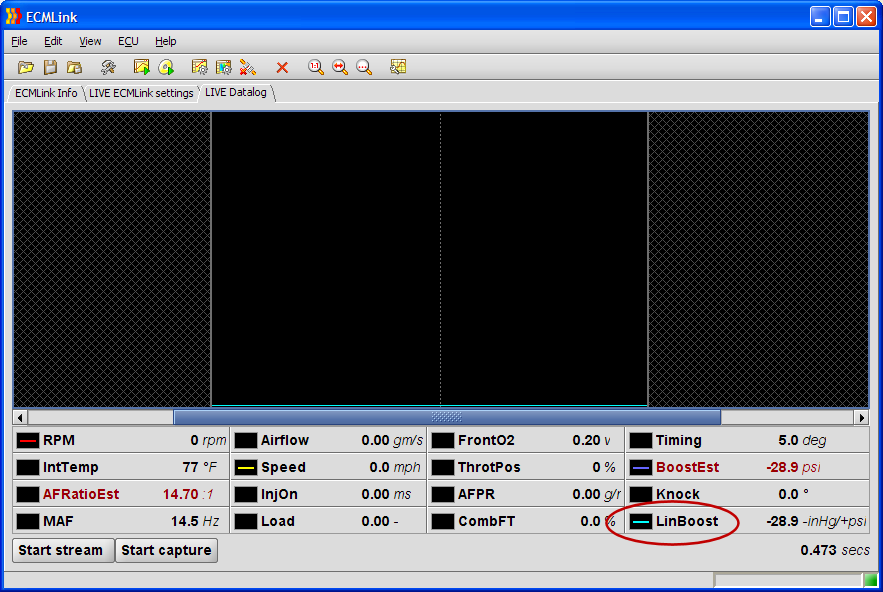
If you right click on the LinBoost item and select preferences, you'll get a dialog where you can configure the boost sensor's properties. This will look something like the following:
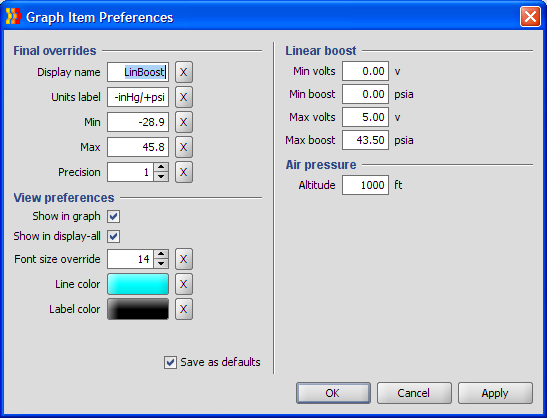
As you can see, the next step is pretty easy. You simply punch in two voltage-to-value pairs from the sensor manufacturer's documentation and you're done.
The LinWideband item works exactly the same except, of course, units are displayed as A/F ratio instead of pressure. However, some wideband units don't faithfully follow the characteristics shown in their documentation. If this is the case, you'll probably need to empirically determine the settings necessary to obtain agreement between the values displayed directly by the wideband unit and those displayed by ECMLink. Probably the simplest way do this is to add RawLinWideband to your displayed values (click the Raw value button on the Display Values dialog). Then lock the ECU in open-loop mode and force a stoichiometric measured (displayed by the wideband unit) A/F ratio (Lambda = 1.0, gasoline A/F ratio = 14.7:1). Observe the logged RawLinWideband voltage. Set Max volts to the observed value and set Max lambda to 1.0. (If you are using ECMLink's narrowband simulation, this observed voltage will also be NBO2 sim's WB switch point.)
Next, determine a Min volts and min lambda point. Force a measured gasoline A/F ratio of 11.0:1 (lambda = 0.75). Observe the logged RawLinWideband voltage. Set Min volts to the observed value and set Min lambda to 0.75. Finish by restoring your normal closed-loop configuration and verify that the ECMLink displayed A/F ratio values match those displayed by the wideband unit.
Page Tools
